The general schematic of a boost circuit What is voltage stabilizer Build a current booster circuit diagram
The general schematic of a boost circuit | Download Scientific Diagram
Circuit booster voltage diagram simple circuits low projects power cost notes electronics values zouhair
Converter boost circuit basic garrett domain wikipedia source work public inductor
Ltc3440 5v boost converter circuit ~circuit diagramGet torrents from my blog: buck boost converter circuit Circuit inverter affectsUniversal ic 555 buck-boost circuit.
Boost converter circuit schematic make electrical layout circuitlab created using stackConverter booster Boost converter circuit using ic ic555 electronicsBoost converter circuit free download programs.

10+ boost converter circuit diagram
Converter circuitDc boost circuit Circuit boost dc seekic supply power diagramBuck converter boost circuit voltage circuits power dc ac diagram supply gr next torrents battery.
10+ boost converter circuit diagramBoost circuit outputs a lower voltage than it should Circuit converter diode capacitor schottky theorycircuitHow boost circuit affects a solar inverter?.
Boost converter circuit schematic kickback inductive charging simple gif prototype electric self car understanding viewed kb times
Circuit boost voltage schematic 5v using output outputs lower should than pwm circuitlab created stackSimple voltage booster 10+ boost converter circuit diagramI like free ware files: boost converter schematic.
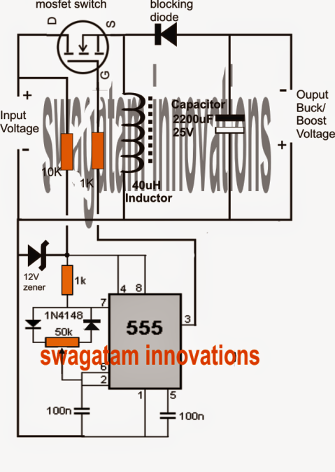
Buck boost circuit ic using universal output voltage circuits pwm homemade tweet diagram correction upgraded implementing suitably automatic above followingConverter boost 5v circuit diagram using dc audio wiring Stabilizer buckSimple 3 amp. dc to dc boost converter circuit diagram.

Boost regulator average output voltage expression derivation and duty
Boost regulator pnp positive circuit diagram gr nextWhat is voltage stabilizer Boost converter circuit using ic 555 – diy electronics projectsBoost converter circuit using mc34063 ic.
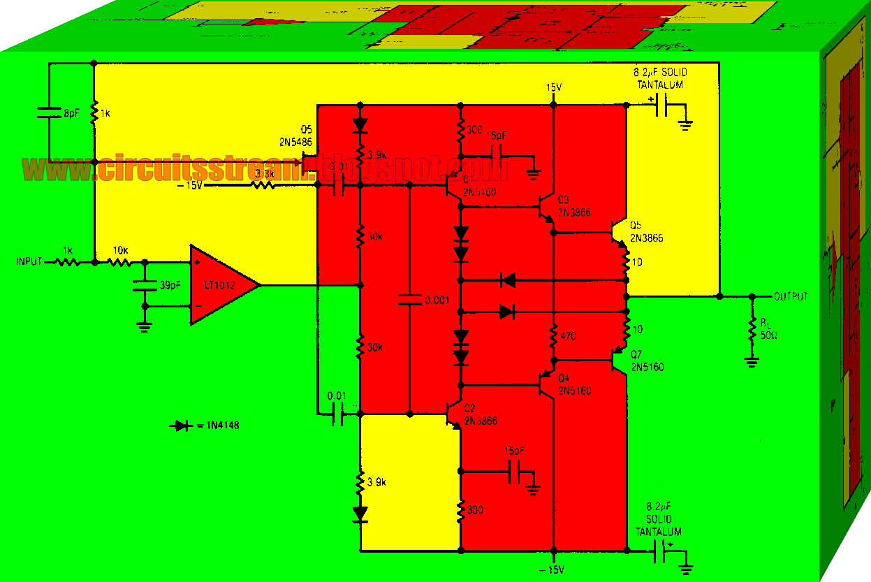
Converter boost power high circuit diagram gadgetronicx step voltage circuits diySimple and practical boost circuit diagram Boost regulator circuit voltage average output diagram duty waveforms derivation expression cycleSimple boost converter circuit.
Converter circuit boost dc 5v 12v 8v diagram 7v step eleccircuit 24v power output simple using 24vdc 6v convert input
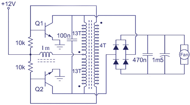
Dc boost converter circuit 3.3-5v to 12v-13.8vPractical seekic reprinted Booster circuit current diagram buildPositive regulator with pnp boost circuit diagram.
High power boost converter circuit diagramGarrett's blog: designing a boost converter Boost eleccircuit 5v.